
[This is part 3: part 1 builds a tank model, part 2 adds a control valve model.]
Now we get to the real purpose of why we have built a model - to add a controller to test our strategy.
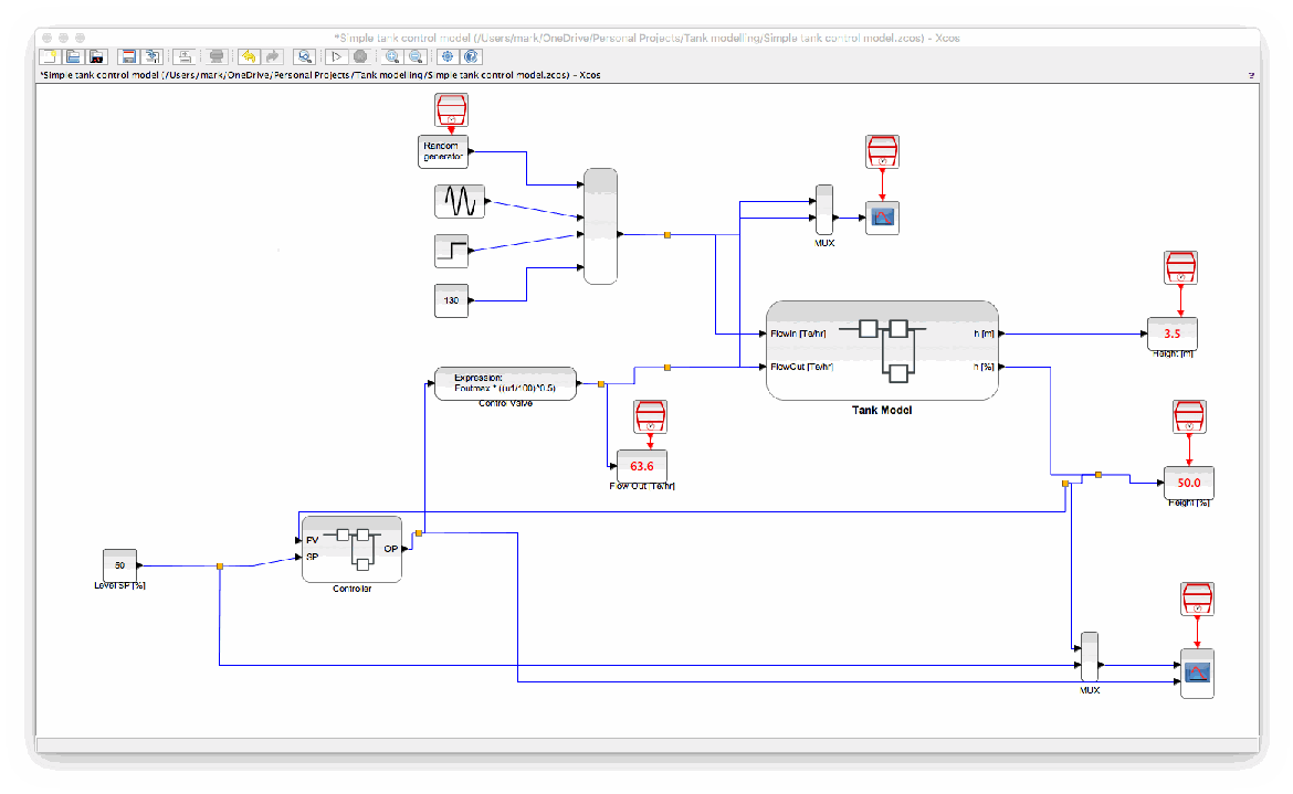
Our new controller is added as per the following diagram...

With the detail of the controller block being...
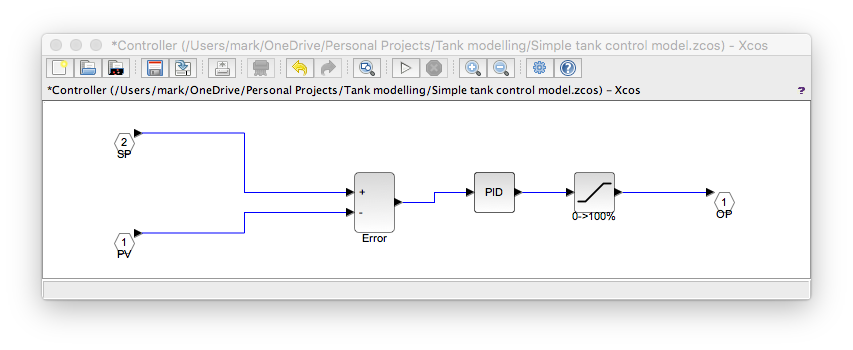
The block after the PID block is a "saturation" block in Scicos terminology. It limits the output to, in this case, 0->100% since this is the physical limitation of the valve.
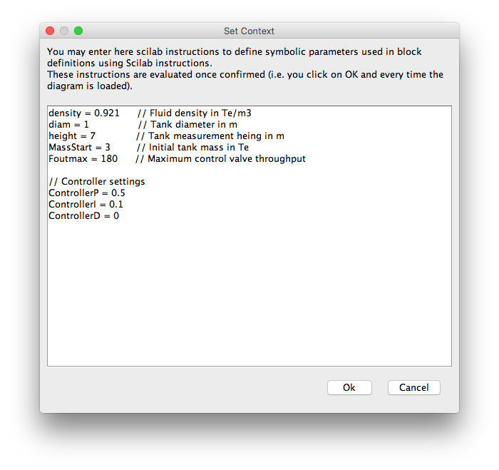
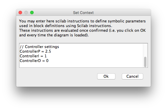
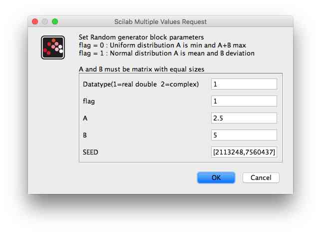
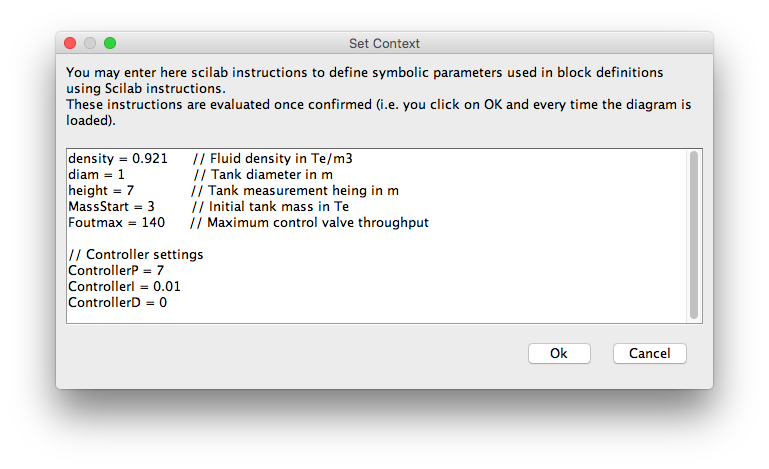
And here is the context. I have chosen the P & I terms at random (badly!). Notice that I have also added some commentary via the "//" mark-up to assist in understanding.
The flow in has been modified too and is now more complex than a simple fixed flow - this is to give the controller something to work against and test how good it can control in real-world situations. The flow in is now an addition of;
- a random element (normal distribution of 5 averaged around 2.5)
- a sine wave (magnitude 20 with frequency of 0.01 rads/s)
- a step change (-50 at t = 900)
- a constant (130)
These disturbances and values have been deemed similar to those expected on the real plant.
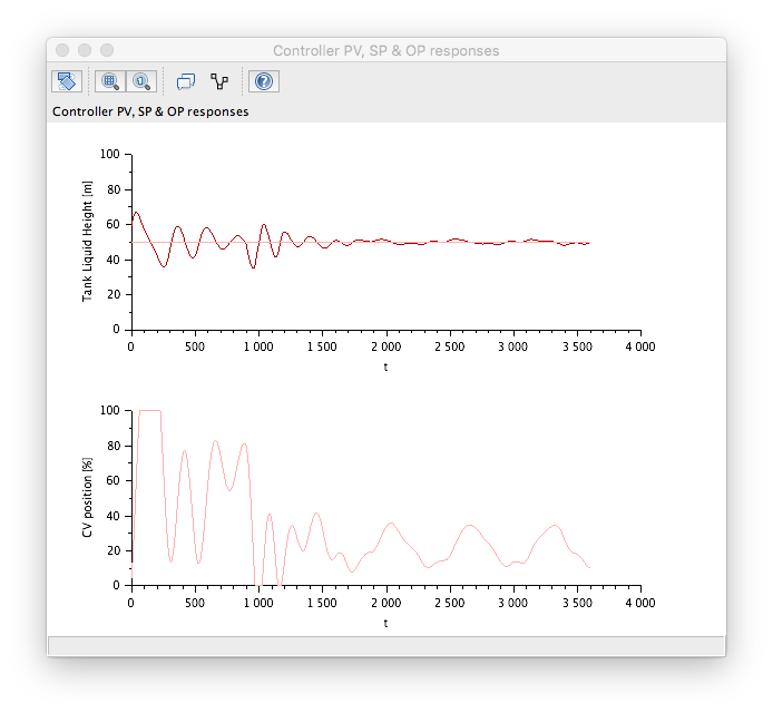
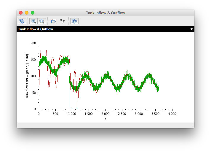
So what response do we get with this?
Well our control is stable and the level does settle down but it is not that impressive. At the step change point (t = 900) there is a large disturbance that takes some time to settle down.
Changing the tuning settings gives a better result...
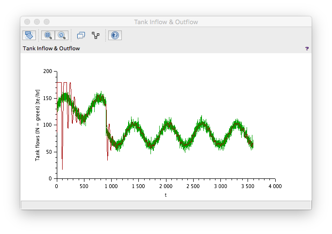
Note that the inlet flow is identical even though we included a random element. This is because the seed is the same which results in the same random number pattern (it is pseudo random!). This is great for testing as it allows the same disturbance to be used each time.
A bit more adjustment gives even better performance (this is not the best though).

So the answer to "while my proposed control philosophy work in principle?" is "Yes!".
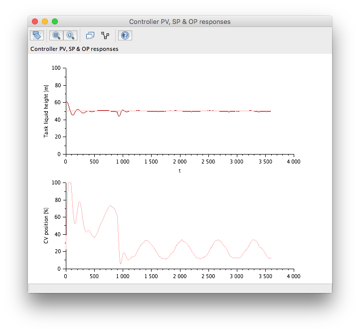
And this is all very intersting and sort of useful but you are not going to get accurate tuning predictions from the above model to use on your real plant because the model fidelity is not high enough. However, the purpose of "real enough" modelling is not to solve this kind of problem but to rapidly check if concepts can work. Suppose we change the maximum valve throughput to 140 Te/hr. A bit of re-tuning is required because the dynamics are different (again this is not the best that can be achieved but this is not the purpose of this exercise).
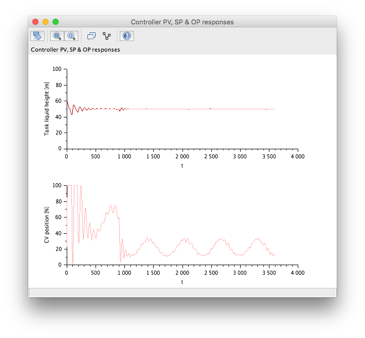
And this context gives the following response...
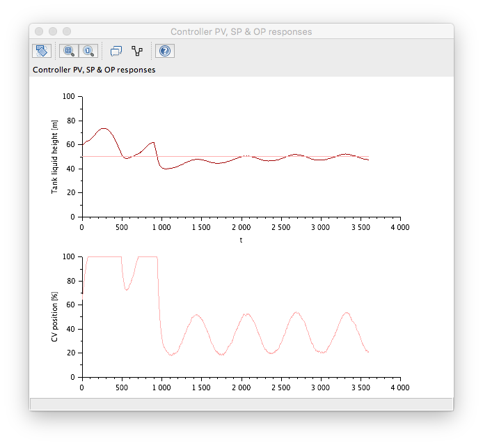
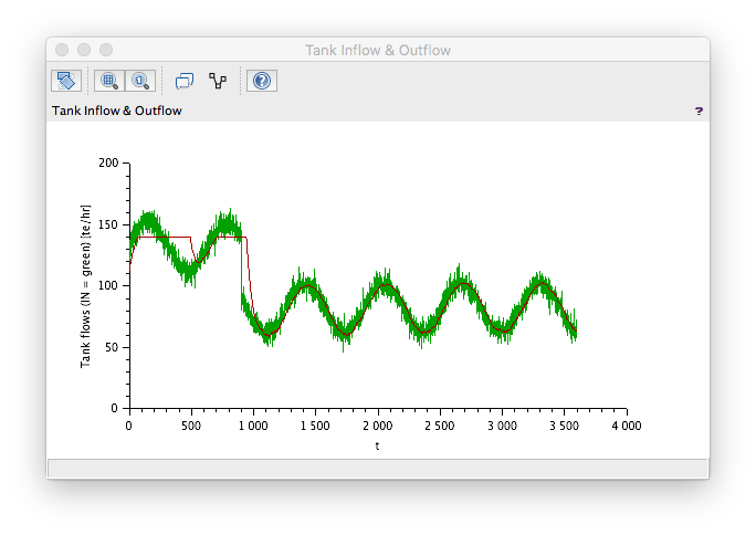
Which is sort of OK but the controller is struggling at times (outlet CV is fully open on occasion) and there are some rapid changing and cycling moves in the output too. The amount of error obtained may also not be satisfactory. You maybe able to get better performance with further re-tuning but it should be apparent that the proposed scheme will struggle .
So the answer to "while my proposed control philosophy work in principle?" this time is "It will struggle!".
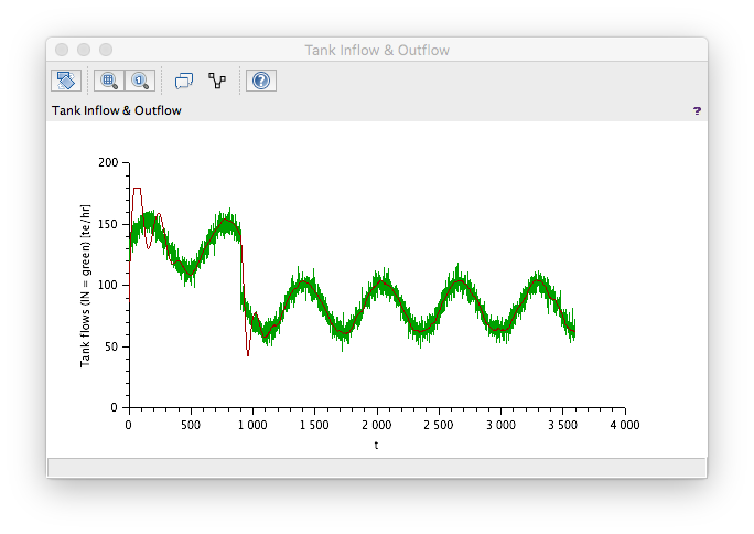
Obviously the outlet valve is too small to cope with the expected variation and this would have been obvious in this case from looking (the inlet flow is reaching 160 Te/hr so your outlet valve ideally needs to be capable for a flow greater than this). However, the "real enough" model backs this up and in only slightly less obvious cases it can take a lot of number crunching to be able to determine if a valve is big enough. By building a "real enough" model you can quickly test the concepts and get a feel for the dynamic response which you can share with engineers from other disciplines.
Previous Parts